|
|
|
DuMont 181 Restoration
The sixth pre-war
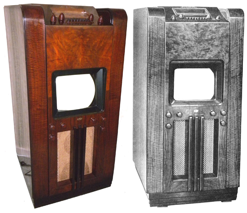
television added to my collection is this 1939 DuMont Model
181 television with radio, original price was $540.00.
Electrically & mechanically it is nearly complete, just
missing the knobs and some radio trim pieces. The
cabinet is structurally sound, but will need some new veneer
and a couple of pieces made. I plan to document the
restoration here as I make progress on it. I am hoping
to have it completed by the end of 2009.
|
|
|
|
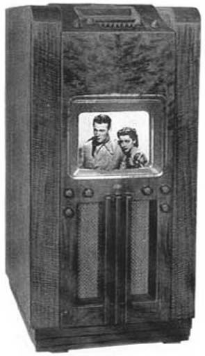
The set as shown in an early Dumont catalog |
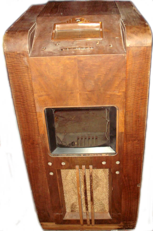
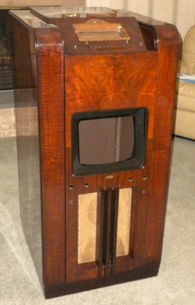
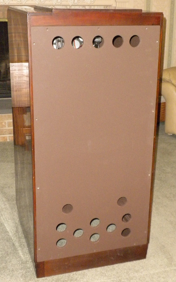
My cabinet |
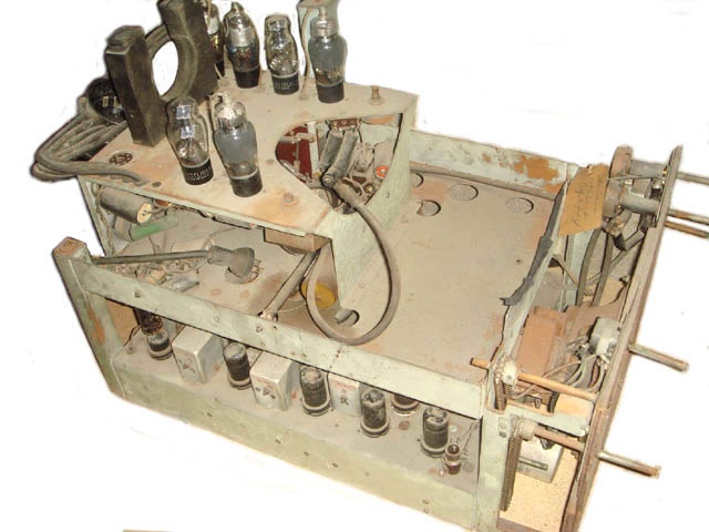 |
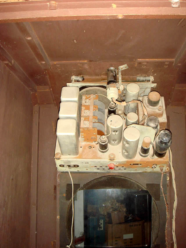
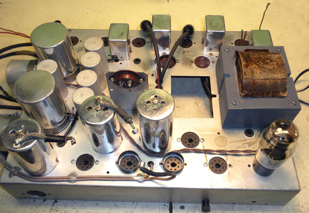
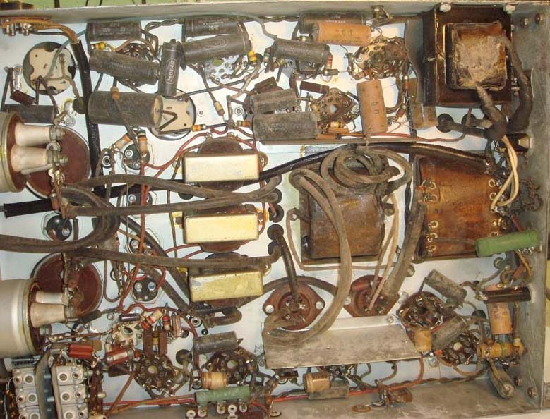
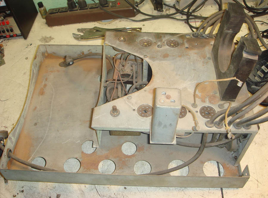
The chassis is complete, there are a couple of items that have been damaged over the years. One shaft has been snapped off and a couple of the control shafts are bent. Dirty and surface rust. |
 |
 |
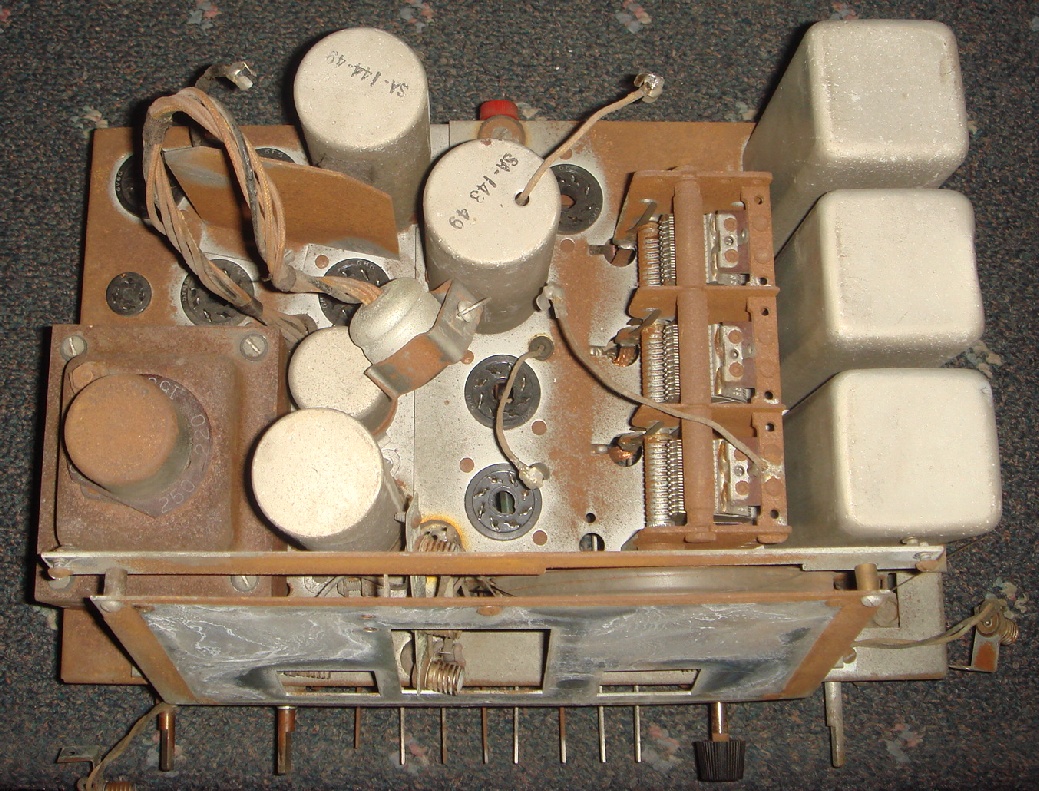
After inspecting the chassis and comparing it to schematics in Riders, a few differences were uncovered. In the upper right corner of the chassis above, a new filament transformer for the CRT has been added. You can see the original wires coiled and secured to the shield near the center transformer, I don't yet know if there was a problem with the original or if it was an engineering change. |
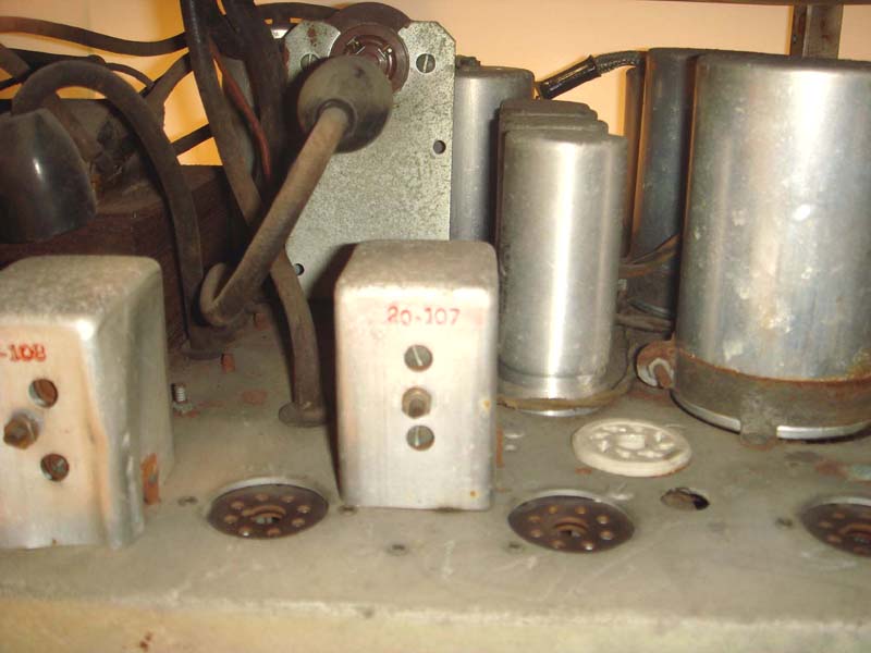
In this picture you can see the new HV rectifier socket that was added to produce the needed +4000vdc for the 2nd anode connection of the later style CRT's. The -4000vdc rectifier socket is behind the IF transformer (20-107). |
|
|
This shows the addition of a coil assembly wired into the horizontal oscillator/deflection circuits. I haven't traced out the circuit to see what it is doing. |
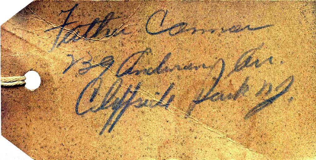 |
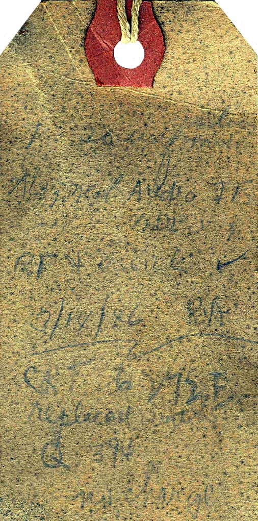
Repair tag that was found attached to the
chassis, this side notes the owner's name and address. I
believe it reads:
|
|
|
The reverse side of the repair tag appears to have a description of work done to the set. I was able to decipher a few lines with Photo Shop using various color gradients.
(Unreadable)Aligned Audio IFRF & (unreadable)3/14/46 R.A.CRT 6 V72 FReplacedQ 396No Charge |
|
Above the radio front panel, missing are the
knobs, pushbuttons and pushbutton bezel. This Andrea radio
is similar to that used in the prewar
Andrea 2F12, and 8F12 televisions.
|
|
|
|
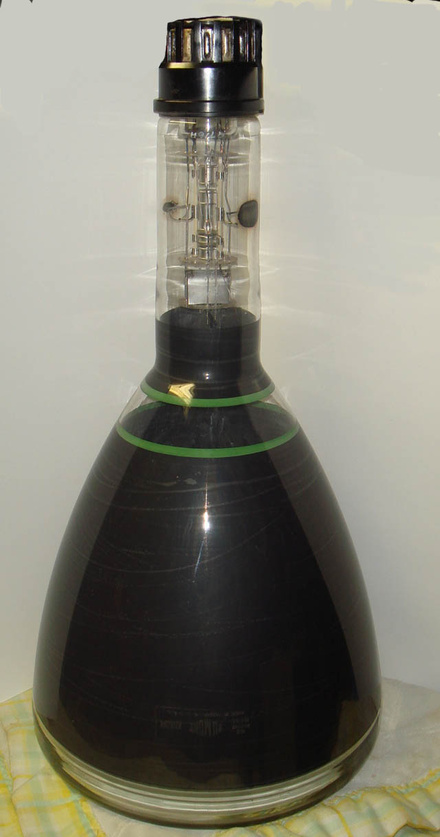
The CRT is a K1003P4 (12"), the post war
replacement for the original 114-9-T or 14AP4 tube. This one
is dated 1946, the tube is still under vacuum but I don't
know if it is a working tube. I will be testing it in
another Dumont set soon.
|
August 12, 2009Not much has been done with the set since the last entry, I have located a source for the high voltage wire used for the CRT socket. It is an exact match for the original. No updates on the new knobs, I will be taking the cabinet to the cabinetmaker before Labor day. Still no luck locating an Andrea radio to use as a donor, getting to think they are as rare as a prewar TV. Have been able to purchase all the missing tubes, all Arcturus branded as originally in the set. Haven't been able to find a spare 6R6G. Probably going to miss my 2009 completion date. |
|
December 25, 2009 Well, I definitely will miss
my restoration date for 2009, maybe summer of 2010.... I was able to locate a glass beading machine that I could use to clean the chassis on this set. Last week I took the radio chassis there and cleaned the 70 years of rust and crud off. |
|
|
|
|
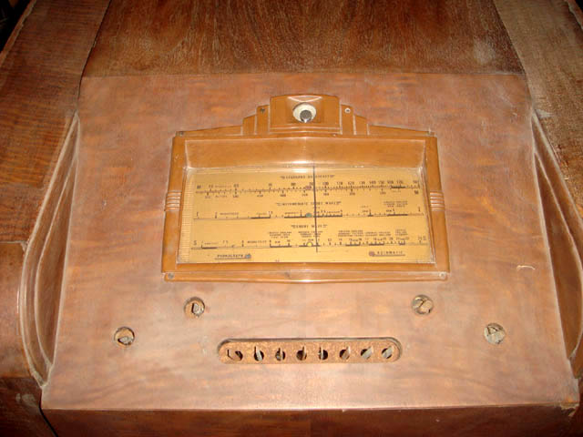
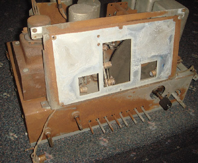
The front of the radio chassis before glass beading. The dial plate has been removed. |
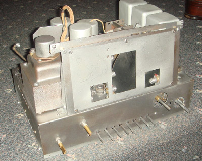
The front of the radio chassis after glass beading. |
|
|
|
|
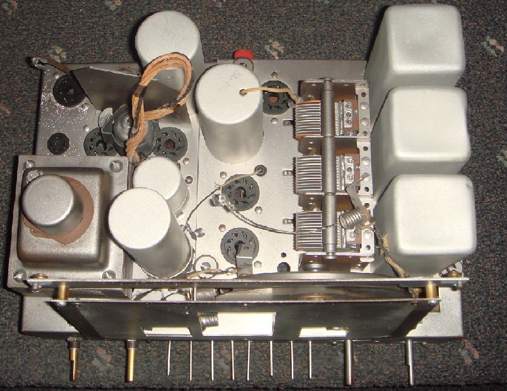
The top of the chassis before glass beading. |
And after glass beading |
| The glass beading does a
great job of removing the rust, but it does create other
problems. The glass beads turn into glass dust after hitting
the chassis, this dust gets into everything. After beading
the chassis all the controls & moving parts need to be blown
out with high pressure air and then washed out to get all
the dust out of all moving parts. The other problem is being
careful around wires and other "soft" parts, even if you
don't blast directly on to the piece the over spray will eat
insulation off wires and remove markings very quickly. I
didn't cover the tube sockets and the over spray removed the
tube number ID that was printed on the sockets, peeled the
insulation off the dial lamp wires and also I managed to
remove the voltage selection labels around the switch at the
top of the transformer. When I do the TV chassis I will need to take extra precautions to not repeat these mistakes. |
 |
 |
| Underside of the radio chassis showing the restuffed capacitors. The cement end seals are broken out of the shell and the old contents removed, the body is heated and wiped clean of the old dirt and wax. A new capacitor is installed in the body and wax is poured into the shell to seal the unit. |
|
January 15, 2010 The cabinet has been delivered to the cabinetmaker, I'm hoping for an April completion. Started to disassemble the TV chassis, I have the front and the chassis supports removed. The front is made of plywood and is starting to delaminate, so I am going to have a new board made. The TV speaker and some of the chassis parts have been glass beaded to remove the rust and corrosion. I've ordered plating material to re-plate the metal pieces with chromate, a safer replacement for cadmium, cadmium is too toxic to do at home. |
 |
|
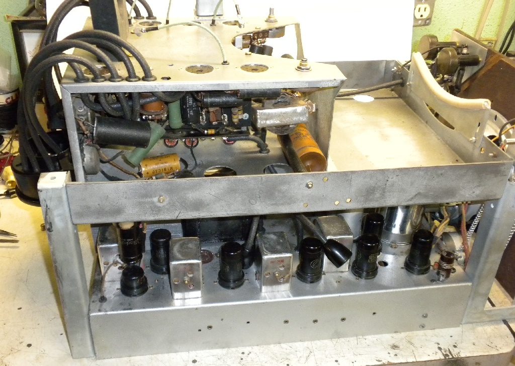
The top chassis which is the sync separator and sweep circuits. |
|
|
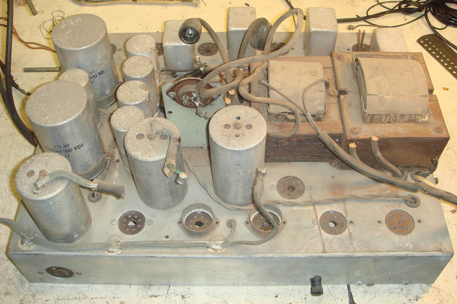
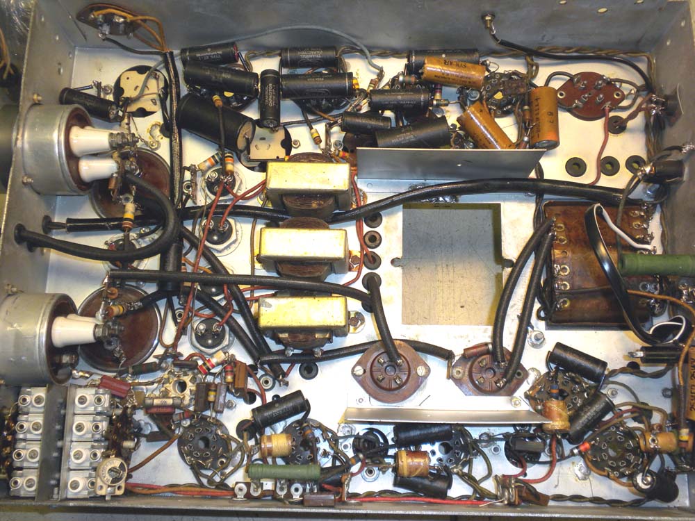
| The bottom chassis
containing the HV and LV power supplies, video and audio IF,
and tuner. The next item on the check list is to test
the power transformers. I will remove them from the chassis
so that I can clean the rust from the laminations, if they
are good I'll repaint them and cleanup the best I can. If
bad they will be shipped out to be rewound. The large HV capacitors I will open and put modern capacitors inside, the LV capacitors are the single hole mount style, hard to re-stuff so I have new that are very similar to the originals.
|
|
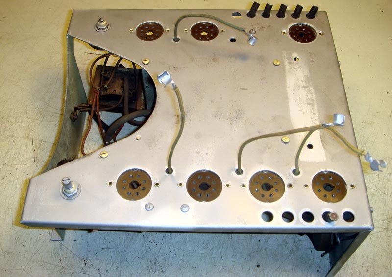
January 24,2010 I've disassembled the chassis' and cleaned the top sweep chassis and middle shelf with the glass beading machine.
I began removing components from the top of the bottom chassis in preparation of cleaning it. After removing the two power transformers and testing them - MAJOR setback, the high voltage transformer is bad. This transformer supplies both the 4,000 volt and 1,500 volts to the CRT and sweep circuits, one half of the 1,500 volt winding is open. I attempted to repair the break which I was able to find, but it only lasted a few hours. This morning I contacted Harbach Electronics, they purchased the Peter Dahl Company that made custom transformers, about having a replacement made. I sent them all the particulars about the transformer, now I have to wait and see what they can do for me.
|
 |
 |
|
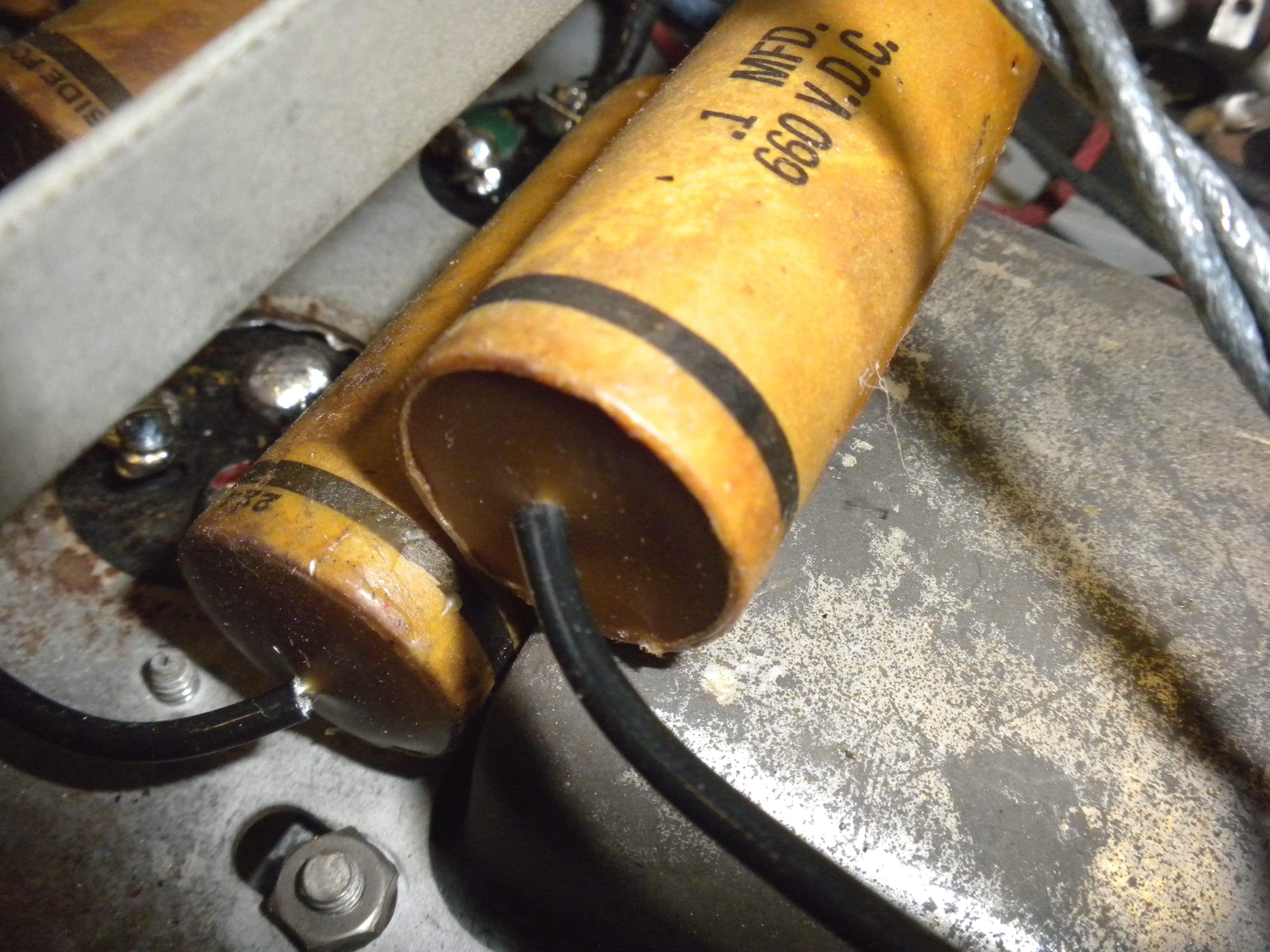
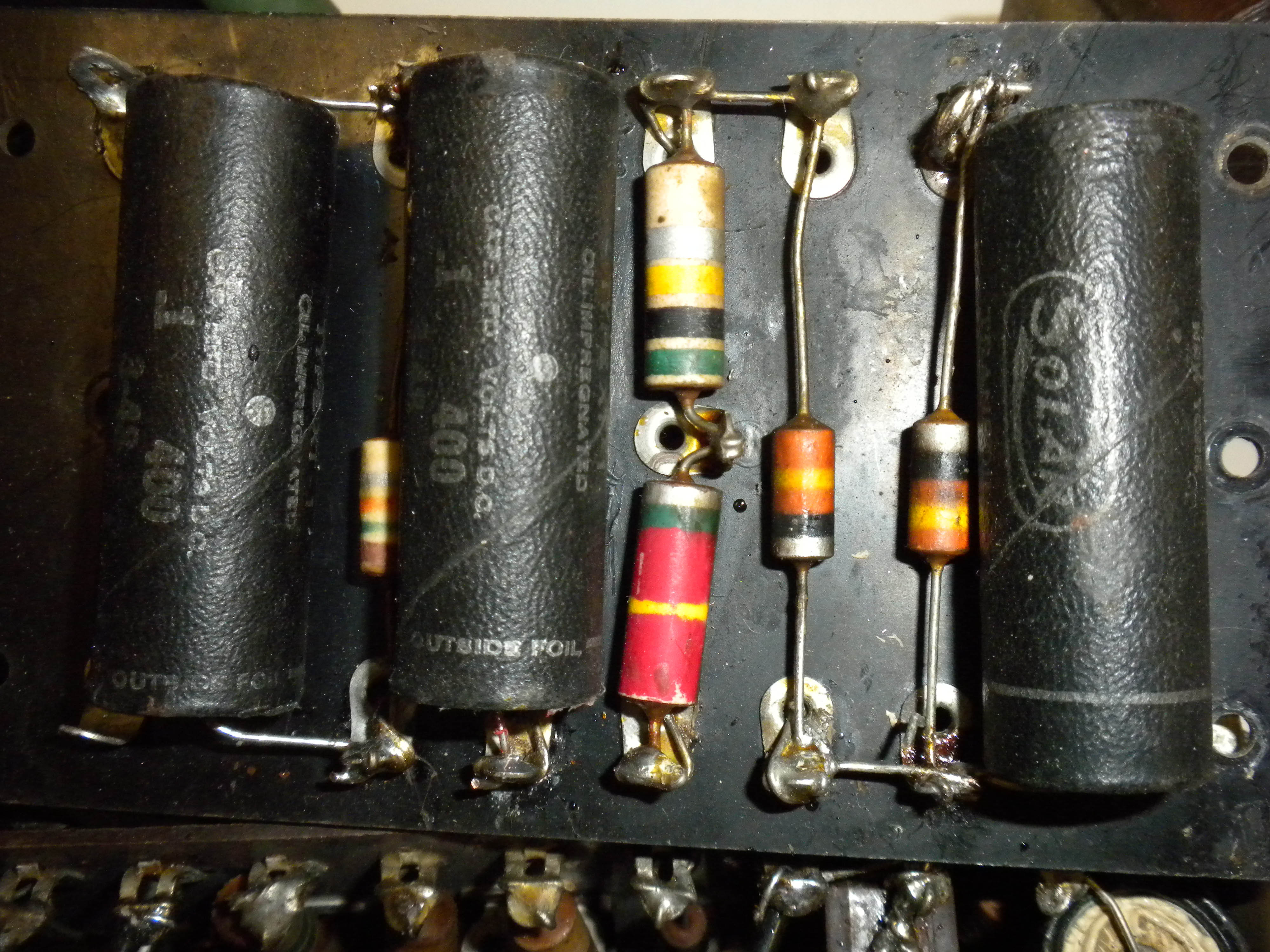
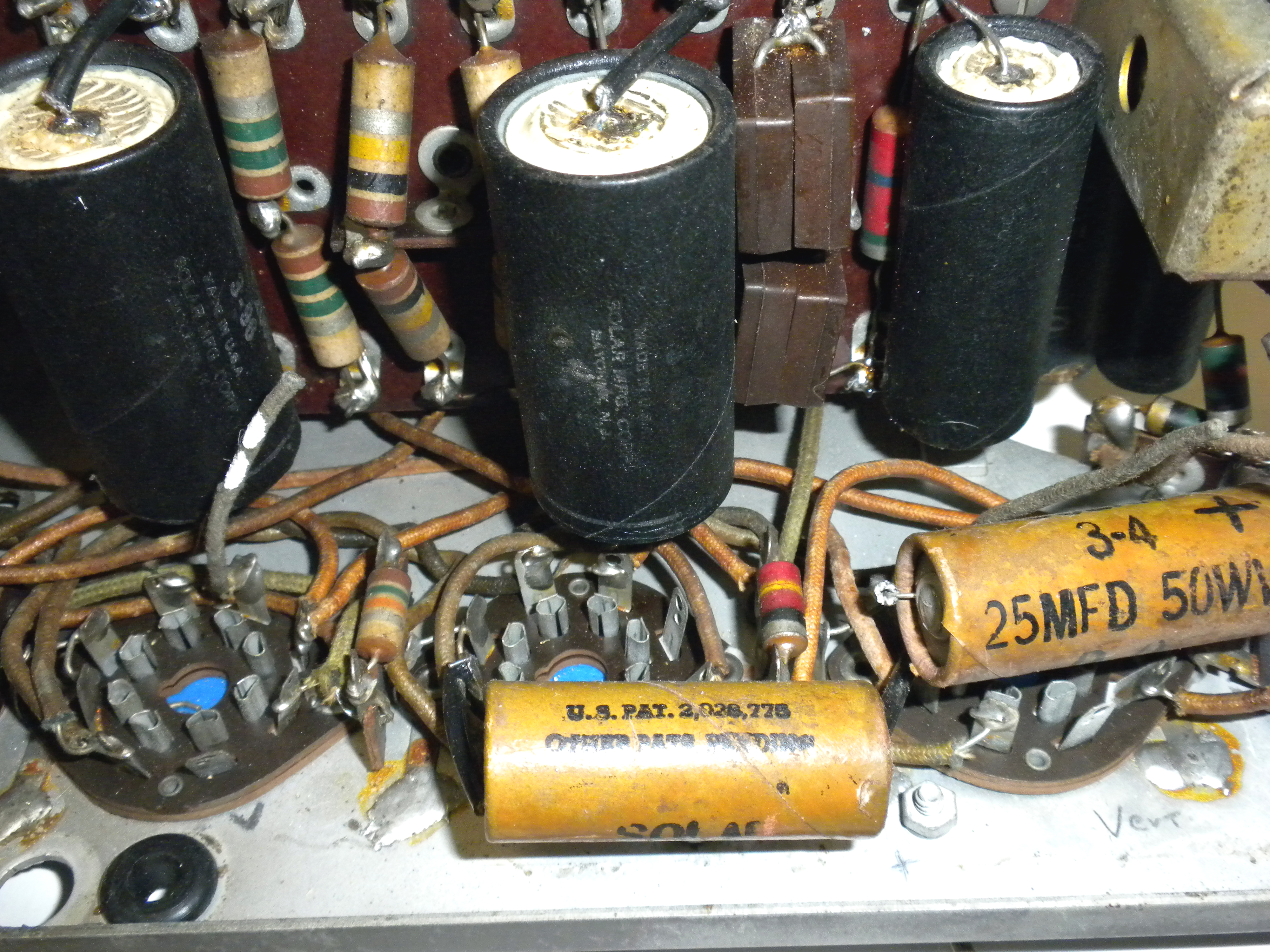
Underside of the sweep chassis shows the restuffed capacitors, each capacitor was opened on one end and the old contents removed, these were oil filled units so the old shell was cleaned of the oil and new capacitors were installed inside the shell. A new end plate was made from heavy cardboard stock, the original metal eyelet was installed and the assembly was reattached to the end of the shell. |
|
February 22, 2010 The HV transformer is ordered, they quoted me a 3-4 week lead time and $400. I hope to have it in hand by the end of March. Another slight drawback, the place that I ordered the reproduction HV wire is out of stock. I have re-stuffed all the HV condensers with modern units. Rebuilding them turned out easier than I had thought. I used a cutoff blade on a Dremel to cut around the crimp edge of the can, separated the pieces then dug out the old paper and oil. Cleaned up the inside of the can with lacquer thinner, then soldered the new capacitors to the bottom connections. Using a small amount of super glue I slid the upper can into the lower section and after the glue set placed it back in the chassis clamp.
|
|
|
|
|
|
|
Modern 4.7uF 1,500V installed |
Reassembled Can |
4 x .1uF 4,000V to make dual .2uF |
Reassembled Can |
| The NOS low voltage B+ can type capacitors I ordered to replace the originals ended up being bad, I tried to reform them but gave up and even though a couple seemed to reform I just didn't want the hassle of replacing them again. So I cut them open the same way as the HV units above and restuffed with modern axial lead capacitors. |
|
March 11, 2010 The cabinet restoration is moving along on schedule, it is back together, new veneer installed. I was able to finally find a good picture of the radio knobs and pushbutton escutcheon plate, and I've sent that to the cabinet maker to have those knobs made. Nothing has been done on the electronic restoration for a few weeks as my order for the reproduction HV wire has been delayed, and I need that to continue. |
|
April 3, 2010 The HV wire finally arrived last week and I was able to resume working on the set. The replacement HV transformer is in final testing so maybe I'll have it next week. Cabinet work is complete final finish is all that needs to be completed.
This is the bottom chassis after installing the HV capacitors and LV transformer. I brought up the LV power supply on the Variac and all my voltages were correct and no smoke!
The underside of the bottom chassis with most of the wiring completed, still have a couple of HV wires to run that connect to the top sweep chassis. The hole in the center is for the HV transformer.
Some wiring still needs to be completed here. My next stage is to test the video and audio sections and make sure they are working before moving on to the HV and sweep testing.
|
|
April 8, 2010
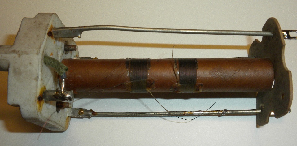
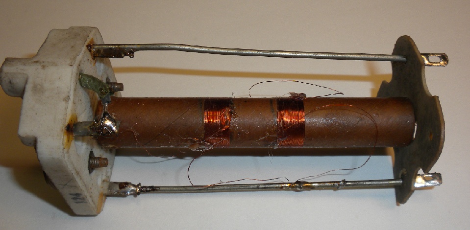
Started testing the video and audio sections, first problem was the first and second audio IF coils were open, actually the wires broke off the connecting supports.
I tried a couple of times to reconnect the wires but they were so brittle they kept breaking off when I put the assembly back in the cans. Luckily the coils are single layer, 28 turns of #38 wire so I decided to just rewind them.
This is the IF coil with new coils. This time the wires didn't snap when re-installed in the can, I now had continuity but still no audio signal. I believe the insulators between the plates of the trimmers are contaminated and shorting out. I decided that I would put the audio troubleshooting aside for now and see if the video section works. I connected a test generator to the antenna input and set three of the oscillators for channels 2, 3, & 4, the last oscillator couldn't be adjusted low enough to use. With this setup I was able to get a signal through the IF stages to the video detector output. I then connected the local cable line to the set and a scope to the grid of the first video amplifier and was able to tune in channels 2, 3 & 4 with a voltage level of about 200mv.
|
|
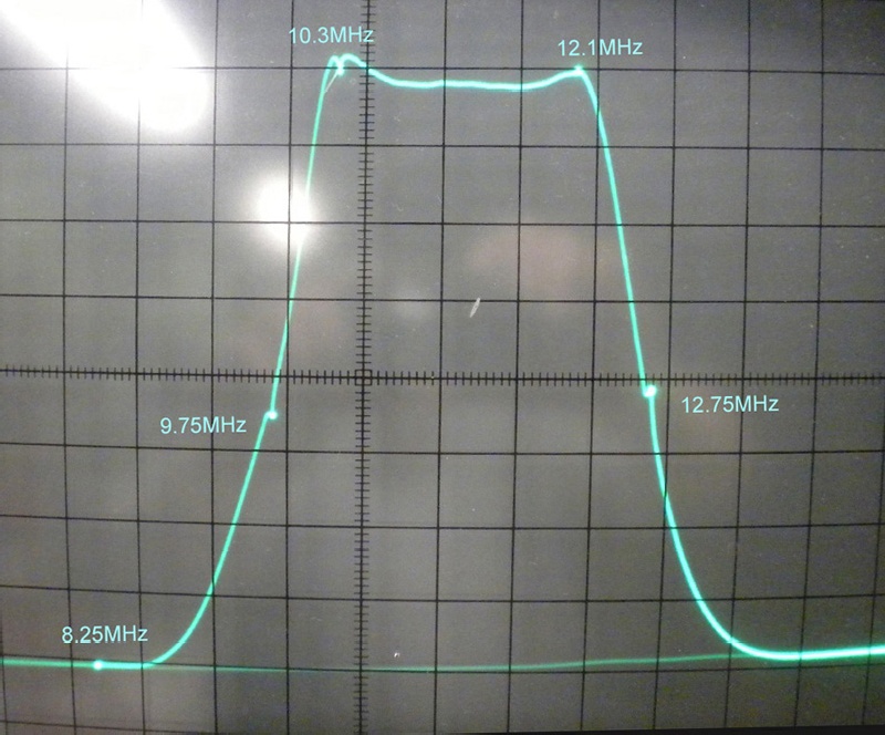
April 19, 2010 After many hours of fighting the rewound sound IF coils I finally was able to get the IF tuned. I then decided to go over the video IF section and after a few hours was able to get this response:
The video bandwidth is about 2.75 MHz, I spent many hours trying to get a bit more out of the circuit but the high frequency end (low side at IF) was pretty much anchored. After checking specs on other prewar sets, I believe this is all that was available at that time. After getting both IF's working on the test equipment I reconnected the cable TV line and was able to align the tuner for channels 2, 3, 5 & 6, video waveform at the detector output and audio quality from speaker were both very good. I can't check the final two video stages as they are constructed on the top sweep chassis and I won't be able to install that until the new HV transformer arrives later this week. |
|
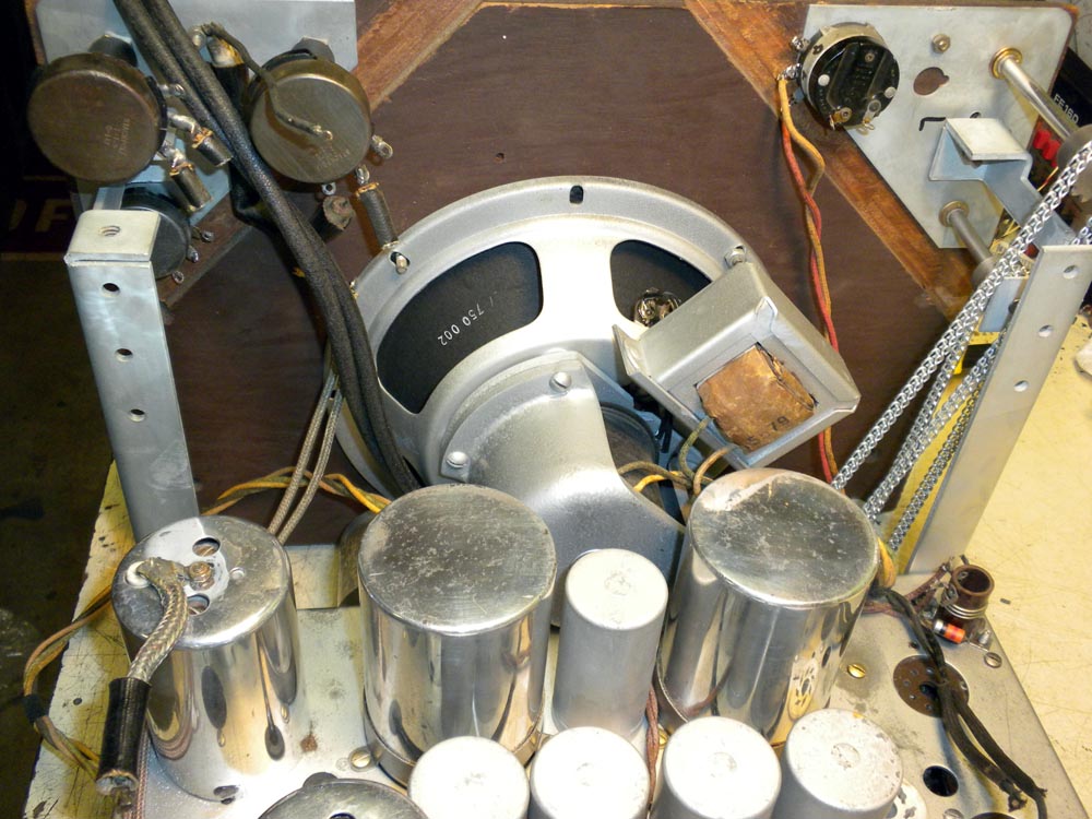
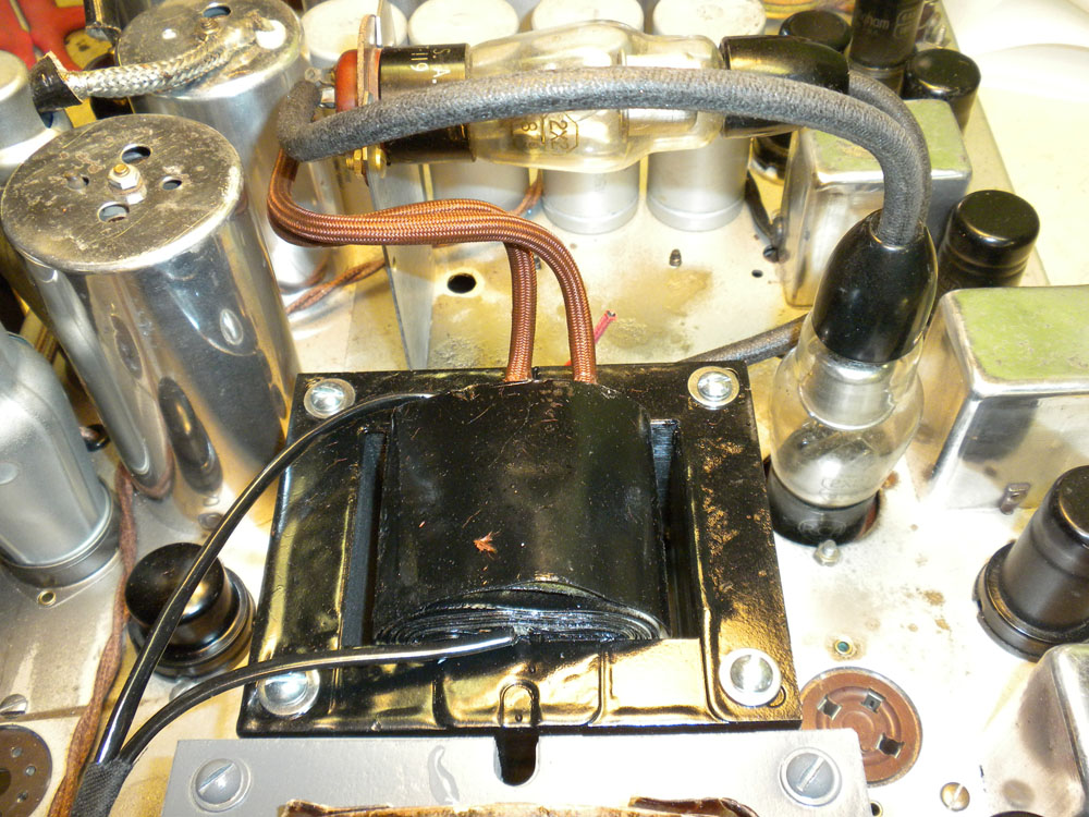
May 1, 2010 The new HV transformer arrived a couple days before I left for the Early TV convention, so I wasn't able to work on the set for about a week. I installed the transformer on the chassis today, I had to drill new mounting holes in the chassis as the original was mounted by two screws in the center of the core the replacement is mounted with four screws on the corners. Here's a picture of the transformer mounted and the primary and one set of HV rectifier wires connected.
The new transformer wires are white silicon which look out of place, so I am sliding a braided covering on as I connect the wires. |
|
May 4, 2010 The restoration is almost complete, I have the new HV transformer wired in and ready for testing. During the initial inspections I found a couple of wiring errors, one was wiring to the two HV rectifiers, the other was that I mixed up two wires from the video output tube. Both wires had been cut to separate the upper chassis from the middle chassis, and I cross connected them, an easy fix.
The finished chassis
After the visual check, I installed the 1,500vdc 5X3 rectifier and brought up the voltages slowly with the Variac, no smoke and good sawtooth sweep waveforms on the CRT socket. The 4,000vdc will wait until tomorrow. |
|
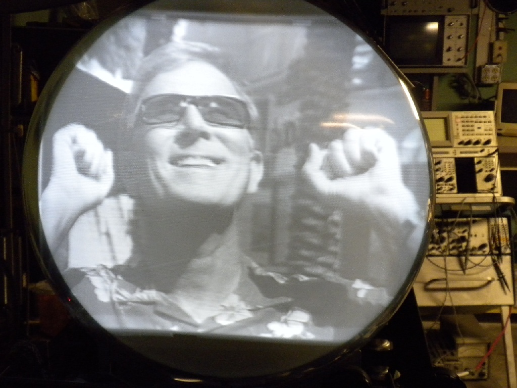
May 5, 2010 Down to the wire, after a year of work I hope to see a picture on the set. I installed the two 2X2 HV rectifiers and again slowly brought up the voltages on the Variac, again no smoke, no arcing and I measure just under +4,000vdc on the intensifier lead. Now for the final test, install the picture tube. Tube installed, powered up and I have a raster, a little fiddling with the 10 controls and I have a picture:
Pure coincidence this ad was running, but it was just the way I felt seeing the set alive again after 70+ years. I still have a few minor adjustments to make and wait for the cabinet to be finished. |
|
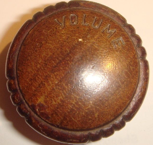
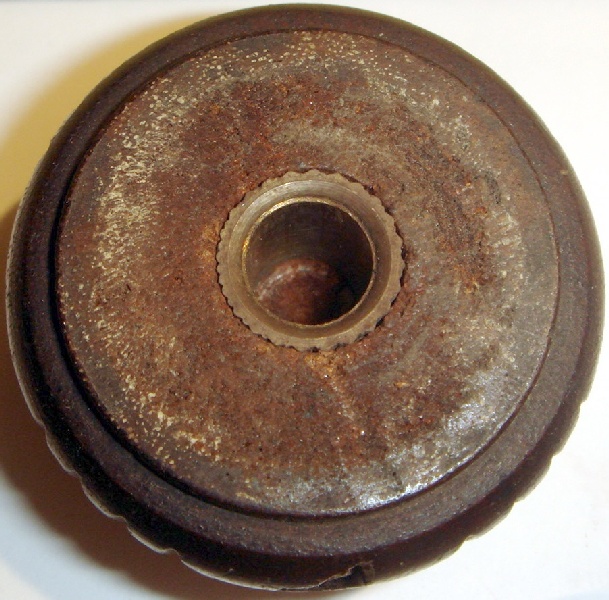
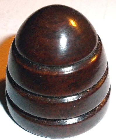
May 10, 2010 The cabinet is finished, the cost came in right around my original estimate. It will be a couple of weeks before I will be able to go pick it up. The new knobs still need to be engraved and the brass inserts need to be inserted like the originals shown below:
|
|
June 12, 2010
Picked up the cabinet today, what a difference from a year ago, looks like it just came off the assembly line. Another cabinet brought back from the grave by Kahl Restorations. Here's what I've been waiting for: BEFORE AFTER
There are still a few things to correct, the radio chassis needs to be shimmed slightly to the right to put all the controls in the center of the holes in the cabinet. The first set of push buttons for the radio are 1/4" short so new ones will need to be made, forgot to take into account the thickness of the escutcheon plate. And I have to center the height of the CRT on the chassis so it lines up with the mask.
The new back. I had no sample of the radio knobs that were used on this set, just a couple of bad pictures of them on the cabinet. I was able to find a fairly good picture of this model Andrea radio and had these knobs and the TV knobs made by Kahl Restorations.
The knobs will be shipped out this week to have the necessary inserts installed.
|
|
July 6, 2010 The knobs have been received with the inserts installed. The chassis and CRT are installed in the cabinet. Here's a comparison of the Model 181 in 2010 and an advertisement from 1939.
I thought everything except the engraving of the TV knob labels was done and I could call this project finished, but a few problems popped up. The biggest is that I hadn't noticed how chewed up the end of the channel selector shaft was and when I tried to tighten down the knob set screw on the shaft, it wouldn't. So I will need to disassemble the parts and have a new shaft made. The other two problems are mostly aesthetics, except for catalog pictures I didn't know what the radio pushbuttons looked like, so I had a set made to match the radio from the Andrea 2F12 set. They turned out beautifully, but I didn't allow for the height of the escutcheon plate so they didn't protrude enough to push them in. So, another set was made 1/4" longer these were perfect in length, but the color is too dark and doesn't match the radio bezel or the wood color, so another set will need to be made. I want to thank Darryl Hock for his excellent work in making the new control shafts that were damaged and the inserts on the new knobs, Steve McVoy of the Early Television Museum for the use of parts from his DuMont set to make replacements, Ed Schutz from Renovated Radios for the radio pushbuttons, Brent Kahl from Kahl Restorations for the beautiful restoration of the cabinet and Jeff Weinberg from Harbach Electronics for working with me on making the replacement HV transformer. Without their help and abilities this set would never have been restored to working condition.
|