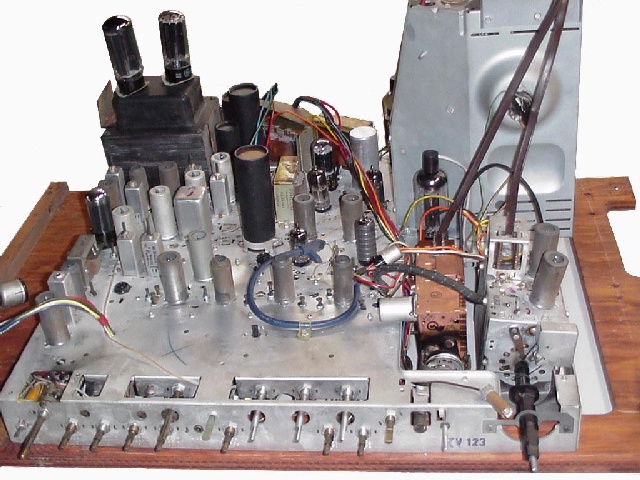
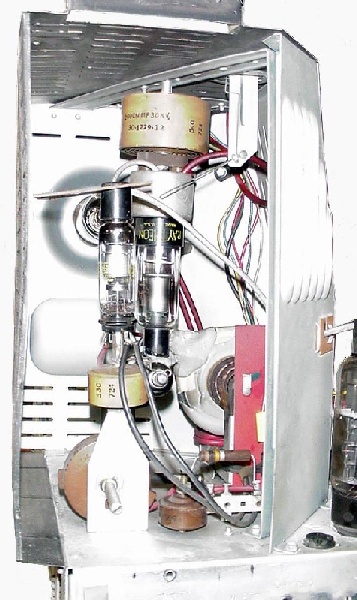
 High voltage cage uses two 3A2 & one 3A3 tubes. In the upper right corner
you can see the HV safety interlock, this shorts the HV to ground when the
back of the set is removed.
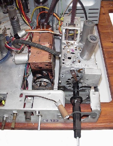
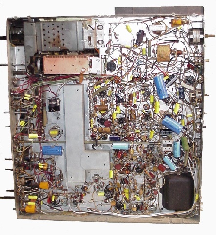
After finishing the recap job and reinstalling
the chassis in the cabinet, I had no HV. Looking into the HV cage I could
see the HV rectifier plate glowing a nice bright red, not a good sign.
After some troubleshooting I found that all the HV doorknob capacitors are
shorted and I've ruined 3 HV rectifiers, luckily they are inexpensive
tubes. Disconnecting the HV filter cap, I do have HV as long as I don't run
the AC input above about 85V, after that the other caps breakdown. I am in
the process of searching for new caps.
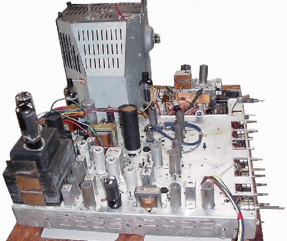
After replacing the HV capacitors
the high voltage was restored and I have an excellent picture. The only
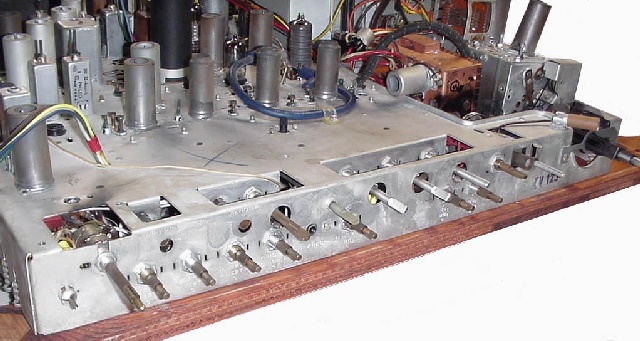
remaining problem is to lock in the color. The reactance tube plate coil
which adjusts the 3.58 oscillator to lock to the received color burst is
bad. It seems that over the years the coil form has shrunk so that the
slug freezes when turned more than 2 turns. I have tried another coil from
one of the spare chassis but it did the same, and while trying to free the
slug it cracked. Luckily the coil is only one layer of number 42 wire and
not exotic, so I am going to get new coil forms and build new coils, as I
expect to have the same problem with the second set I am restoring.
|