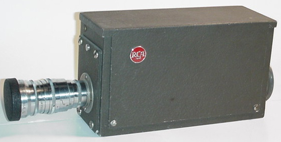
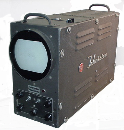
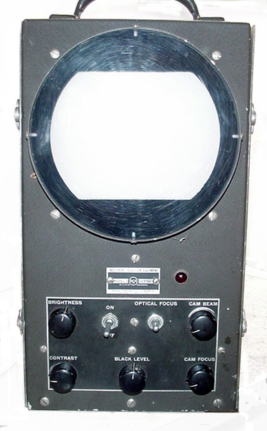
RCA Vidicon Camera


RCA's 
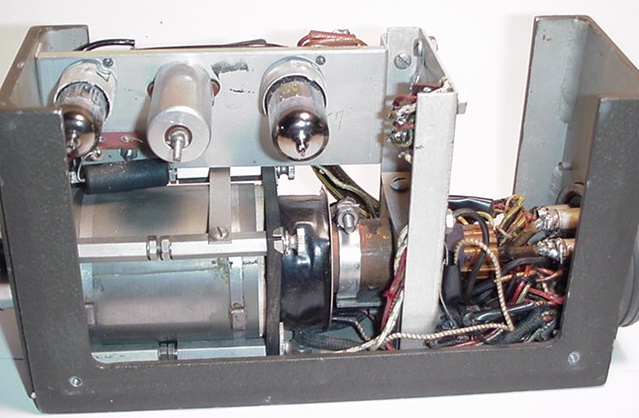
first vidicon camera system from 1950. On left is the camera and lens, on right is the camera control unit (CCU). The 
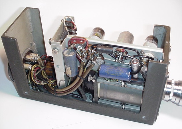
camera body contains only the vidicon tube, two stages of video gain, and deflection coils (pictures below), all other 
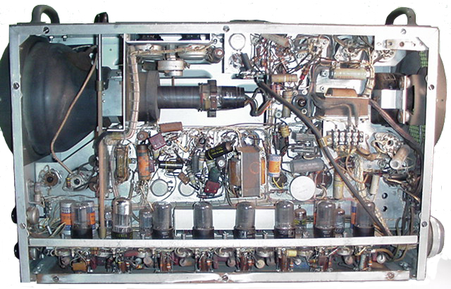
voltages and signals are supplied from the CCU, which is typical of broadcast camera systems.

Except for the original tripod, the system is complete, although it is not functional presently as there is a loss of B+ somewhere in the CCU, after the rectifiers. Tracing wires is a nightmare as all the wires are tightly laced and color coded wire is almost non-existent, also there is a power resistor on the lower deck that is disconnected and I cannot tell where it should be connected or if it is even needed, and lastly there is an empty socket on the main chassis that I have no idea what was connected to it. Really need a schematic.

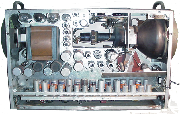
Since the original posting I have been able to get a raster on the monitor screen. The loss of B+ was due to a time delay relay that had bad contacts, cleaning the contacts and reseating the armature has fixed that problem. Leaky/shorted capacitors were the next problem, all tubular electrolytics and molded paper capacitors were replaced. All the can 
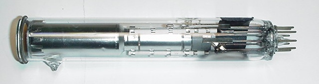
electrolytic capacitors check out good. I believe the vidicon is bad, and I'm waiting for a replacement.

Through a friend I have tracked down some documentation for this unit that may help in making it functional again.


6326 vidicon tube


Inside components of the camera. Construction appears all hand made. The vidicon tube presently in the unit is a 6326 which I am sure is not what was originally in the unit. Originally it used an  RCA 6198 tube, the first production  vidicon. The 6198 was designed for studio applications, the 6326 was for use in film chains. Another clue is in the present tube connections, the 6198 has 4 grids using 3 connections, grids G3 & G4 are internally connected to pin 6. The 6326 has 5 grids using 4 connections, grids G4 & G5 are internally connected to pin 6. The vidicon socket is wired for only 3 grid connections and an external wire is used to connect the extra grid of the 6326.

You can find additional information on the early vidicon tube here.

You can see a very early Philco vidicon camera here.


This side view shows the timing chain that develops the sync frequencies. The master oscillator runs at 31.5KHz, then divides down for the 15,750 Hz horizontal and 60 Hz vertical frequencies.


This side view shows the video amplifier. This appears to be more of a production unit than the camera construction. It may have been a production CCU for an IO camera that was modified to work with the vidicon camera. 


Rear of the camera unit, the connector is the same large size that was used on the 40's & 50's vintage IO cameras. The large connections are coaxial and carry the video and sync signals between the camera and CCU. The CCU has an ID plate identifying it as a Model 1; Serial Number 504. Other than the RCA "meatball" logo there are no identifying markings on the camera unit.


Television  Home