|
|
|
GE-HM-275 Television Restoration
I have decided to start the restoration of the GE HM-275. The power supply needed very little work as the filter capacitors appear to have been replaced within the past 10-20 years and checked OK when I applied a DC voltage and checked leakage current.The RF chassis had been worked on in the past, three of the original paper capacitors were replaced with modern units. The remainder of the caps were original to the set. |
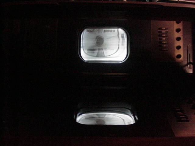
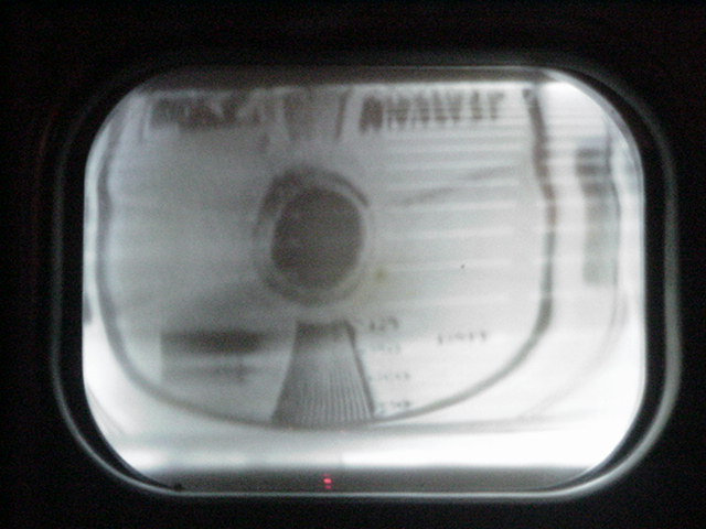
Before starting the restoration I wanted to verify I had a usable 12AP4 CRT. These pictures were taken after carefully bringing the set up to about 80% line voltage to test the CRT. The signal source was a B&K Analyst. |
|
|
|
The TV RF Chassis
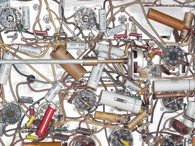 |
This picture shows the recapped RF chassis. The original capacitors were opened up and new capacitors placed inside the original tubes, the the ends were sealed with vintage wax I saved from early Victor potted can type capacitors. I found some early brown capacitors with the correct values imprinted and replaced the three modern capacitors with these. Both electrolytic can capacitors on this chassis were bad, luckily I had some NOS units in my parts supply that were the correct shape and value. |
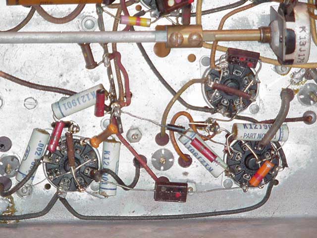 |
Another picture of the recapped RF chassis, this is the AM audio IF section. |
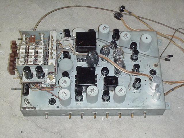 |
The "almost" completed RF chassis. The long flex shaft at the top is for the focus control which is located in the power supply chassis. I would like to have the tube complement on this set have the original tube date codes "X3" or "XE3"and GE labeling. If you have or know where I can get the following tubes with either of these date codes email me.
|
The Radio Chassis
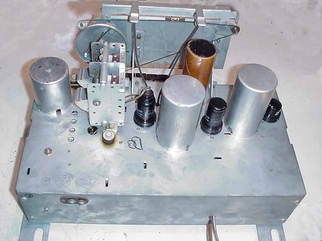 |
The radio chassis has one electrolytic capacitor which was bad and I was not able to rejuvenate it. It is in a cardboard tube instead of the familiar metal "FP" style can. I want to keep all the chassis' as original as possible, so the only alternative was to stuff new caps in the original case. |
 |
 |
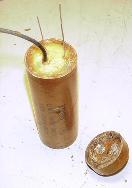
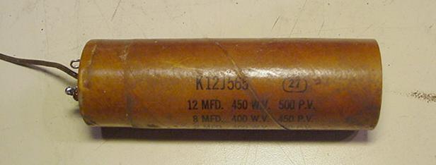
The original capacitor after removing it from the chassis mount. |
Using a fine tooth model saw I cut through the tube in the center of the mounting clamp area. |
 |
|
The original capacitor was 12uf/8uf/8uf. The 12uf and 8uf section were tied together externally, so I was able to get away with only stuffing 2 new capacitors in the tube. I drilled and chipped the old material out until there was enough room to slip the new caps inside. |
After the new capacitors were installed I sealed the void with wax. Then drilled small holes next to the external connections to feed the leads up through. |
 |
The capacitor after reattaching the cut section and making the lead connections. The cut seam was filled with wax and leveled. After mounting in the chassis clamp this repair will be invisible. |
Restoration Status
|
02/15/03 I've put the GE back together, but still have a couple of problems with the set. First is a very bad hum bar in the picture, the B+ lines are clean and I don't hear any excessive hum from the speaker. I believe the HV capacitors may be open as they are listed as being paper, I will have to order new replacements as I don't have any HV capacitors in stock near the required values. With the hum bar it is hard to determine the quality of the picture at this time. Second problem is virtually no recovered audio, I am able to get a 8.25 MHz signal through the IF stages, but because this set uses an AM audio IF and AM detector I will need to retune it to operate as a slope detector for the FM signal. Third problem is a completely dead radio, not even static from the speaker. Hopefully it is just a minor problem, I'm thinking it can't be much as there are only 3 tubes in the radio. |
|
02/17/03 Went back into the power supply chassis today, found a filter capacitor that had checked good is now open, also one of the 879 HV rectifiers was bad. The HV capacitors checked OK. Putting the set back together I now have an OK picture with a very light hum bar. The contrast is lacking, I'll have to go back into the video stage and check for correct voltages, the focus control is against the one stop so I need to check the focus resistor string. I now have noisy audio, not sure if that's the best the AM detector will do. The oscillators in the tuner are off frequency also, the only channel I can receive is (modern) channel 2 (54-60MHz), on selector button 2 with the fine tune control at the extreme end of its range. The correct tuning range for each button should be: Button 1 44-50Mhz Old channel 1 Button 2 50-56Mhz Old channel 2 Button 3 66-72Mhz Old channel 3 Modern channel 4 Button 4 78-84Mhz Old channel 4 Button 5 84-90Mhz Old channel 5 The picture tube has good brightness, but has an ion burn in center of screen. Prewar CRTs did not use ion traps and used straight guns, so after a few hours of use a dark burn area would develop in the center of the screen. |
 |
HBO on channel 2. The hum bar and ion burn are barely noticeable here. |
|
02/25/03 Thanks to Jeff Lendaro I have an earlier schematic of the set circuitry. It appears that when the existing HM-275 models were released for sale in 1941, as the Model 90, there were extensive changes to the video, audio, & sync circuits done, mostly removal of components and some rewiring of circuits. There are still sections of the circuit wiring that the new schematic doesn't show, but it will be a lot easier to create an as-built schematic diagram now. |
|
12/23/03 Removed the radio chassis to work on, troubleshooting I found the B+ lead to the 2nd IF tube was not reconnected when I recapped the set. After connecting the lead I had weak output, realigning the IF stages and RF stage brought the unit back into operation. I retuned the pushbuttons to their original 1939 frequencies for the stations (NY) identified on the buttons.I still have the hum bar in the picture, but I haven't replaced the HV capacitors yet. I also tuned one of the RF sections to channel 4 to be able to use a VCR on the set. Audio is still mediocre due to the AM detector, I will need to remove the chassis to do that work. |
|
6/21/09 It's hard to believe that it has been 6 years since I last worked on this set. I don't have any new updates, since nothing has been done to the set. Five more pre-war sets have entered the collection since this one, maybe next year. . . . . . . .
|