|
|
|
TEK 576 Curve Tracer Adapter for Vacuum Tubes
The 576 Curve Tracer was designed to test solid state devices, i.e. transistors, diodes and the like.
With some additional circuits it can be used to also test vacuum tubes.
I'm going to show how I made a self contained tube curve tracer for one of my 576's.
I'm going to assume you already know what the 576 is and how to use it for SS parts.
The basis of this project is a board that was created by Dennis Tillman in 2017, you can read about it here:
http://www.ke5fx.com/A_VTCT_Adapter_for_All_Tektronix_SCTs_W7PF.pdf
|
|
|
|
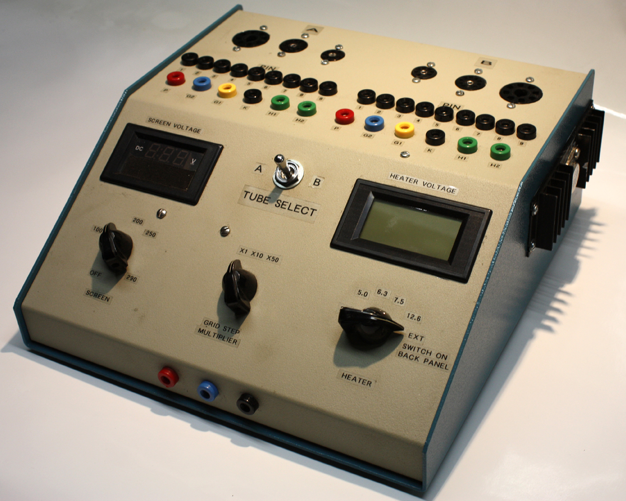
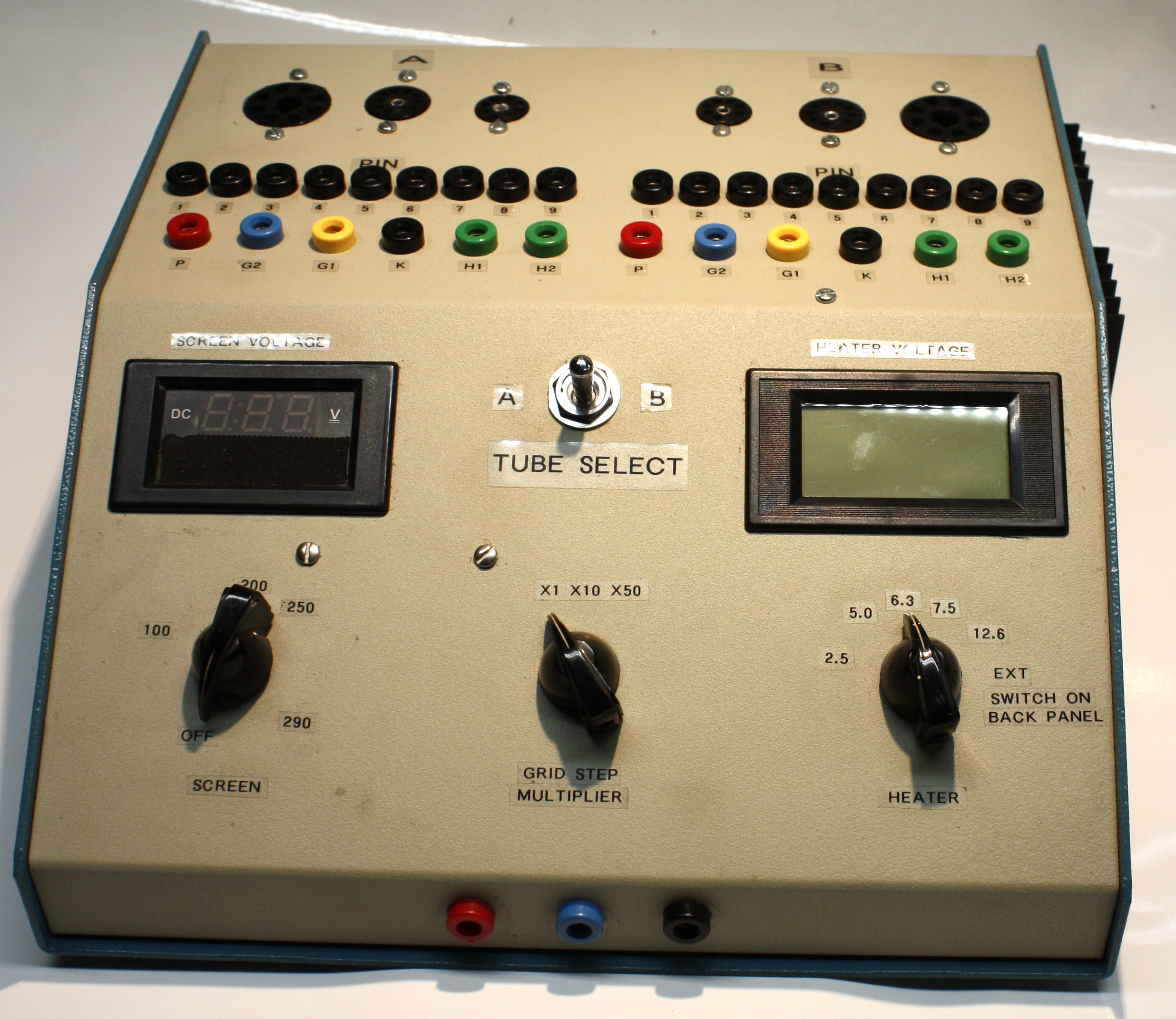
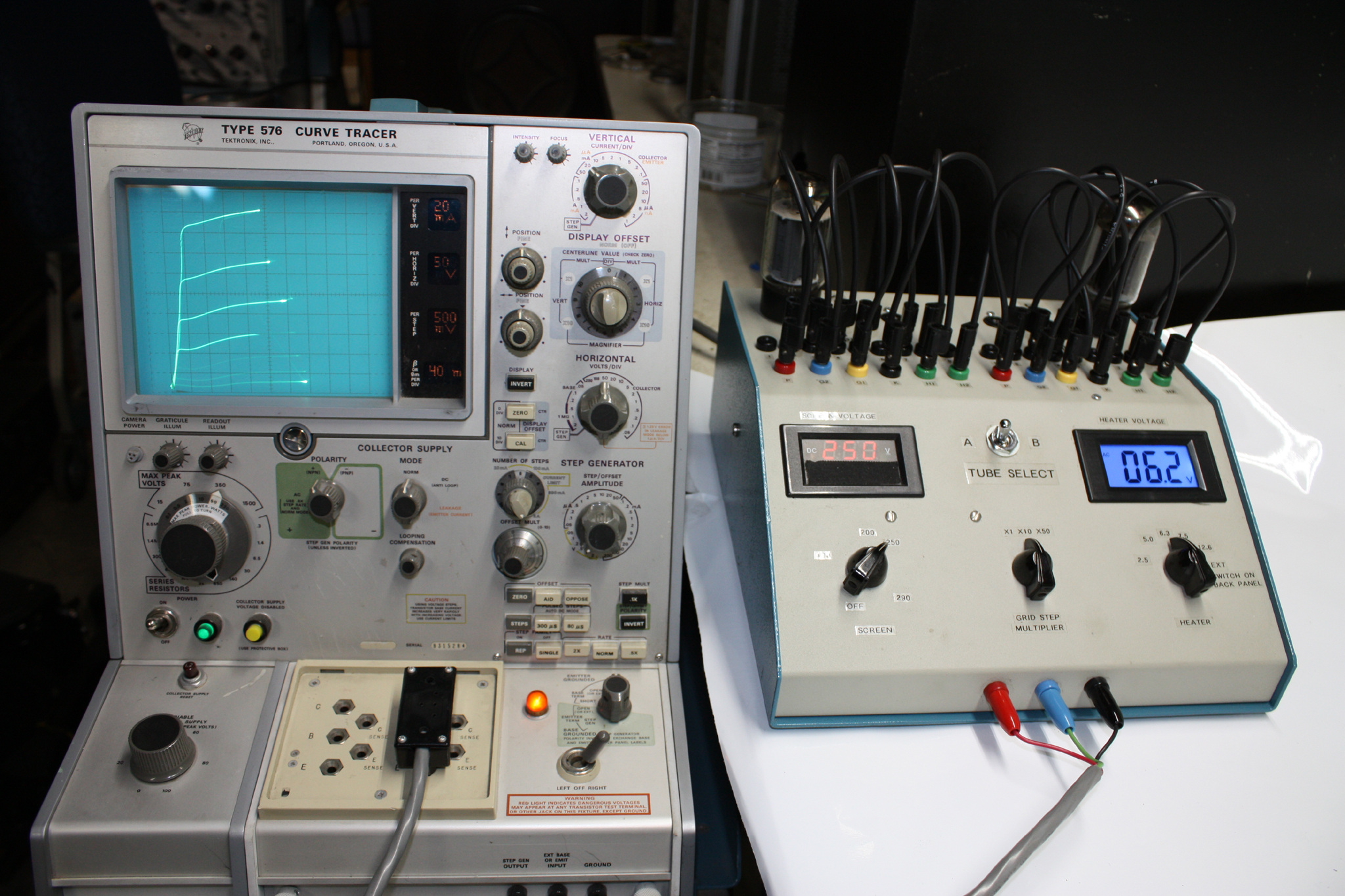
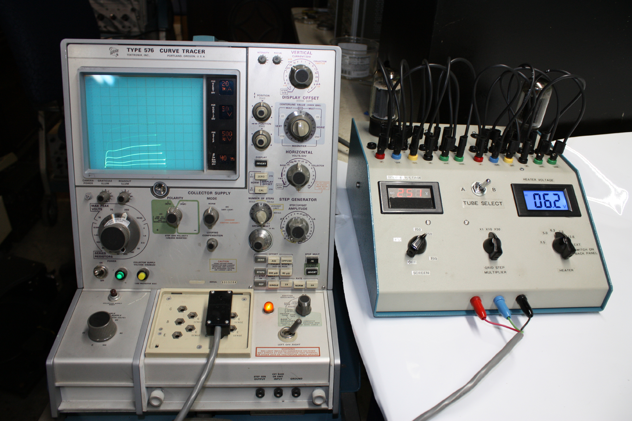
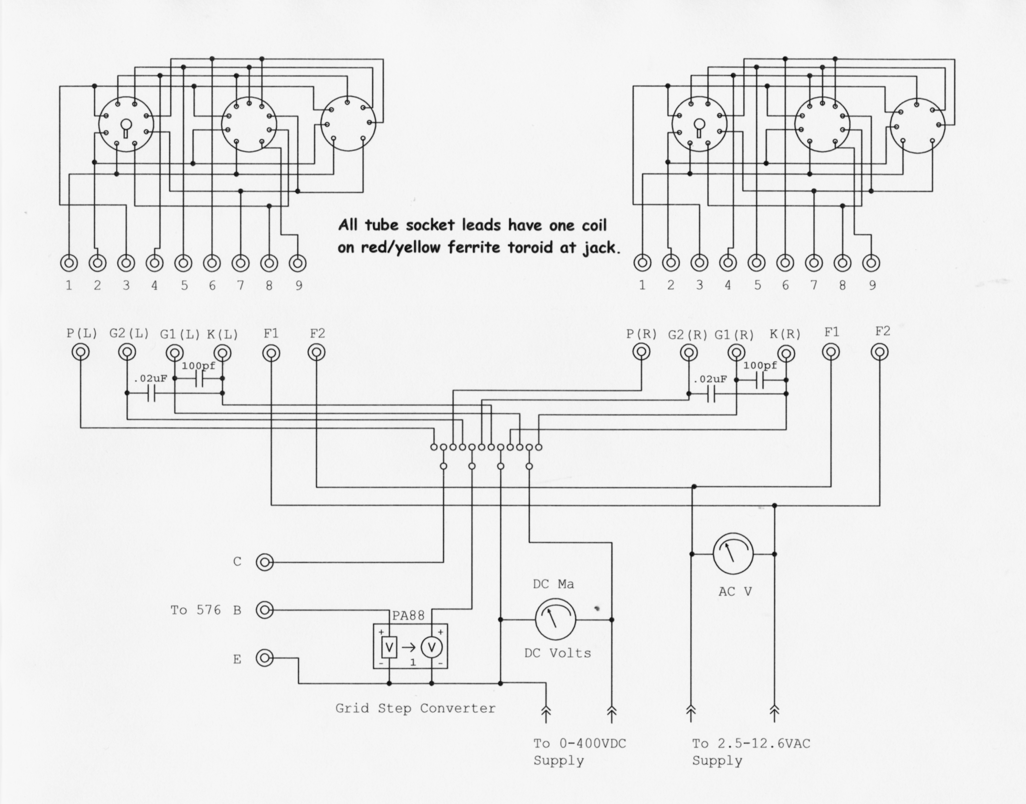
This is the completed tube adapter. It is self contained has 0-400V power supply for screen grid, filament voltages for the most common heater voltages, 2.5, 5.0, 6.3, 7.5 and 12.6 VAC. If the tube to be tested needs an odd voltage terminals on the rear panel can be connected to and external supply. Digital meters monitor filament voltage and screen voltage. Connections to the tube under test is done with jumpers similar to the TEK 570 vacuum tube curve tracer and the Weston 686 vacuum tube tester. Three sockets are on the chassis for the A and B side testing, octal, miniature 9 and miniature 7 pin. If other bases are needed I made adapters to plug in to the octal sockets to test 4, 5, 6, 7, and Loctal pin tubes. |
 |
|
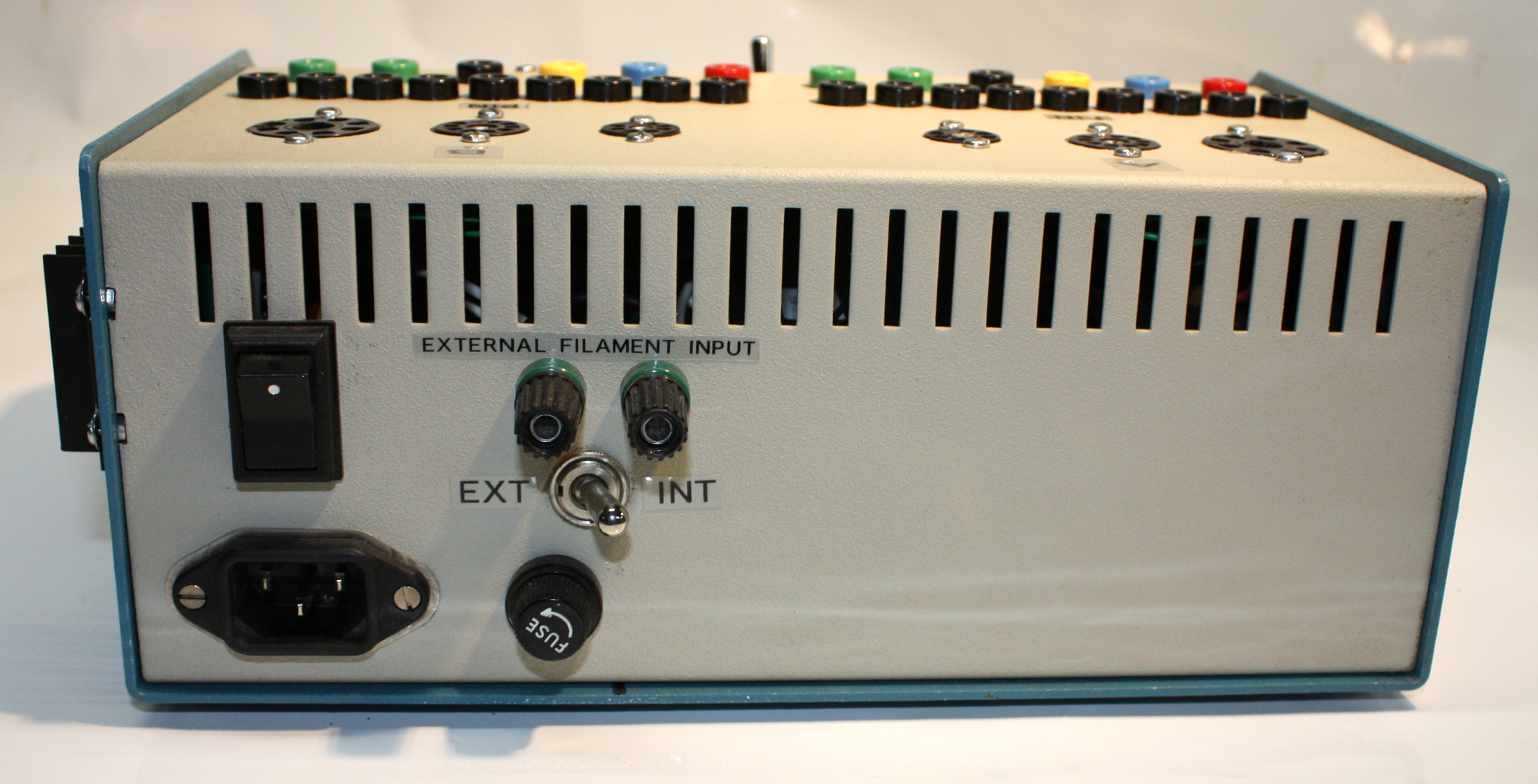
The rear of the adapter has the external filament terminals for tubes with non standard voltage or to use DC on directly heated tubes, power switch, AC input, and fuse. |
.jpg) |
|
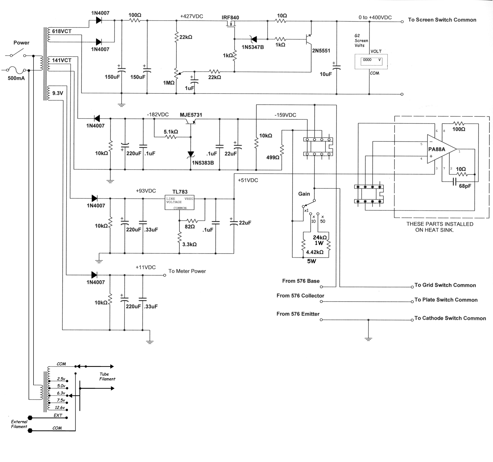
The original VTCT adapter was only able to supply a grid voltage to -50 volts, enough for most small signal tubes but not enough for some power tubes. I made a small change to the design to use this PA88 opamp that is able to supply up to -150v grid voltage. Only drawback is the cost of the device, list price is around $200, I was able to find a source for about $100. |
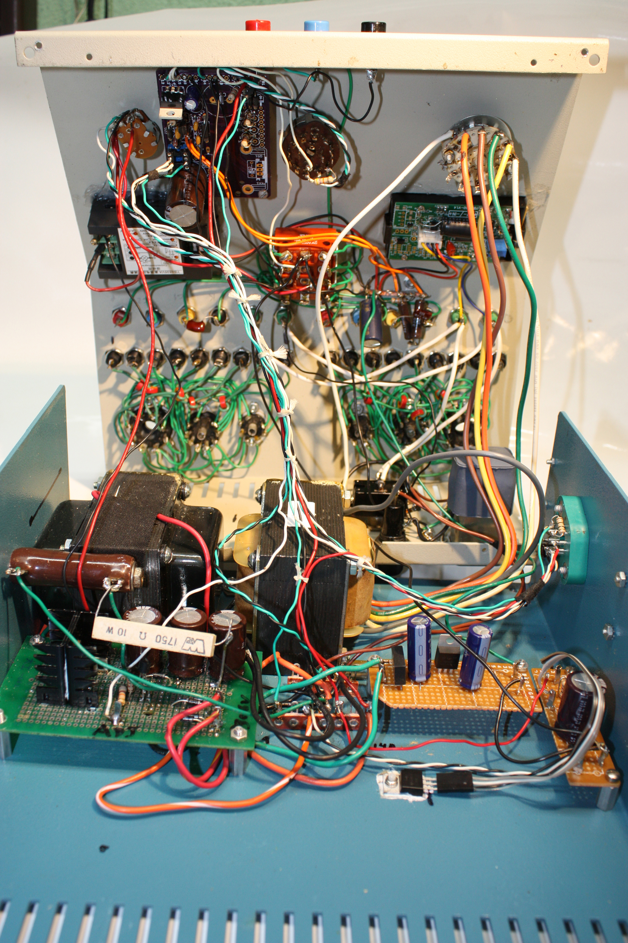 |
| The inside of the adapter, the board in the front left is the 400v screen supply, the middle board is the negative 160v supply to the PA88, the board on the right is the +50v supply for the PA88. The blue board at the top is the VTCT board from Dennis. The power transformer & filament transformers were custom made by Heyboer for this project. I had to add small ferrite toroids to each of the leads from the jacks to the tube sockets to suppress oscillations that occurred when testing high gain tubes. I originally had planned to be able to measure the screen current but the combination digital voltmeter/ammeter I used had to have a common return which meant I was measuring the combined plate and screen current, which might be OK except the plate voltage used on the 576 is not steady DC but pulses so the meter was always changing. If I ever was crazy enough to try building another one I would use individual meters, definitely use a bigger case and a better layout. |
 |
 |
| These two pictures above show the characteristic curves for a pair of non matched 6L6GB tubes, 350v on plate, 250v on screen, the grid step is -5v per step, the 576 is set for .5v/step and the adapter is set for X10 multiplier. Only 6 steps are being generated, as can be seen the bottom tube is much worse than the top one. |
 |
|
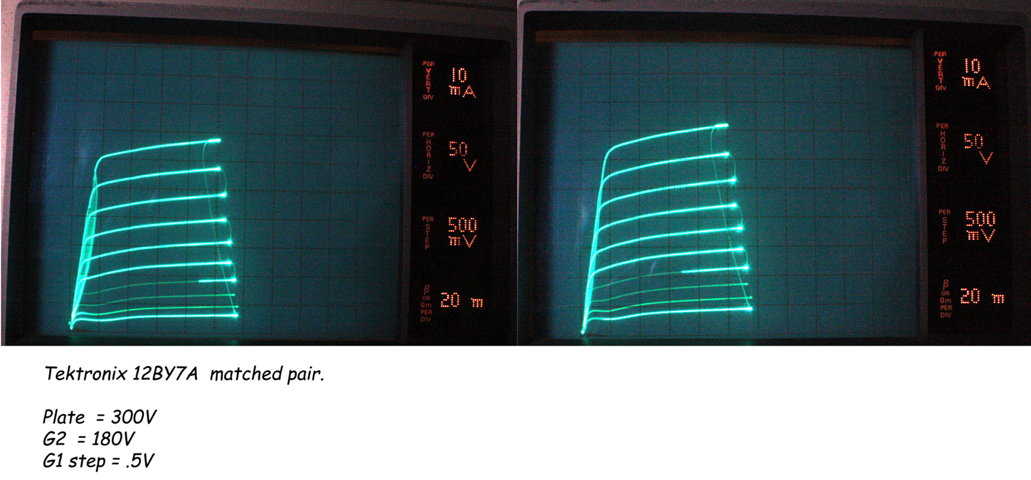
Shown above is the characteristic curves of a pair of TEK matched 12BY7A tubes that were pulled from a scrapped scope. As you can see they are still pretty well matched even after 50+ years. |
 |
 |